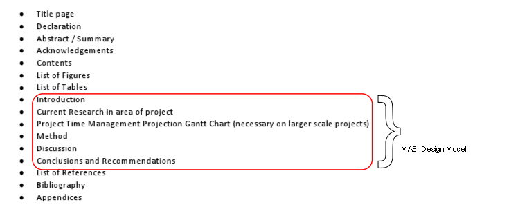
How to use this Model – What is a Systematic/Prescriptive Design Model?
The MAE Design model is a simplified version of prescriptive design model by Pahl and Beitz. The model represents the process a student should follow when undertaking any kind of design task.
Each step within the model has a number of headings that should be considered at each stage. You may not use all of them every time and you may find some bleed into others, especially in the Planning and Clarification stage, however it will highlight significant requirements in each step.
Each heading has some material to support it at the appropriate level. You’ll find some elements are more relevant at 1st year level (L1) and need no further explanation, simply practice and acknowledgement of their importance. Some elements are not required until L2, such as FEA and CFD work; don’t worry if you don’t know what these are, you will one day, but they’re not taught at L1.
Additionally, all material is carefully referenced. You are encouraged to follow-up on these from books available in the library. This document is not designed to tell you everything you need to know, but to point you in the right direction.
As a young engineer, it’s very easy to feel unsure of exactly how and where to apply the sciences you learn elsewhere on the programme. In reality, there is no easy way of solving a problem, but you can take steps to reduce the effort (Hawkes and Abinett 1984: 2).
Therefore it’s important that you know exactly what a prescriptive design model is and what its purpose is. It will help work through the areas highlighted below, taken from the MAE Report Writing Guide for Engineers (This maybe found on CURVE or on Moodle).
Prescriptive/Systematic Design Models
Haik and Shahin (2011: 6) suggest Engineering students can be daunted by the varied sources of new information they are exposed during their studies. They continue to say that without guidelines or structure the struggle to organise information without a clear start point and finishing line, often not making best use of information available to them. Hawkes and Abinett (1984: 10) and Cross (2008: 34) agree that a systematic analytical approach persuades a designer to thoroughly investigate a brief on the minimum amount of information to fully understand the brief and reduce the likelihood of needing to needing to re-work the solution later by losing focus.
How do you decide what to have for dinner? Look at Table 1.
| 1. See what food you have in the cupboard. |
| 2. Think about recipes you know and maybe research new ideas. |
| 3. Decide on the best to suit your mood. |
| 4. Consider if you can make it or need for ingredients. |
| 5. Cook it. |
Table 1 – Dinner making process.
This is simple, it almost doesn’t need to be stated. In its purest form, the fundamental idea of systematic design follows the same process as in Figure 2.
| 1. See what food you have in the cupboard. | Requirements. |
| 2. Think about recipes you know and maybe research new ideas. | Concept ideas. |
| 3. Decide on the best to suit your mood. Select best concept. | Embodiment Design. |
| 4. Consider if you can make it or need for ingredients. | Find best arrangement – Detail Design. |
| 5. Cook it. | Finish, get paid |
Table 2 – Dinner making process defined.
From a Design Brief of “Cook Dinner”, these are simple steps to find a solution.
Design and therefore Systematic Design, is completely dependent on both practical and theoretical knowledge from mathematics, sciences, engineering sciences and art (to provide aesthetic and freeform thinking), synthesised into and application in an iterative process (Haik and Shahin 2011: 3). It then follows a systematic process of comparison and evaluation to arrive at a solution.
Many modern solutions are derived from French’s model of the design process, the first to set out specific titles for each stage; Concept – Embodiment – Detail, as in Figure 1.
Figure 1 – French’s Systematic Design Model.
The model is drawn as a Flow Diagram to emphasise the progression of the process; one stage requiring completion for moving to the next (Cross 2008: 30).
Conceptual Design
“This phase…takes the statement of the problem and generates broad solutions to it in the form of schemes. It is the phase that makes the greatest demands on the designer, and where there is the most scope for striking improvements. It is the phase where engineering science, practical knowledge, production methods, and commercial aspects need to be brought together, and where the most important decisions are taken.” (Cross 2009: 32)
This stage encourages a designer to consider alternating the concept (Haik and Shahin 2011: 35). It’s recommended that a designer produce a minimum of three exclusively alternative ideas here, so detailed comparisons maybe made (Hawkes and Abinett 1984: 2). The ‘need’ or brief that forms the Customer Requirements, may turn out not to the true need at all. For instance, the customer suggests a product needs to be re-designed to reduce cost. Very often a change in supplier will enable this, thereby removing the requirement for a re-design OR, it might simply mean a change of supplier and small update on the current design rather than a completely original solution. This stage enables this sort of consideration and comparison.

Figure 2 – Pictoral description of Conceptual Design stage (Cross 2009: 32)
Embodiment of Schemes
“In this phase the schemes are worked up in a greater detail and, if there is more than one, a final choice between them is made. The end product is usually a set of general arrangement drawings. There is (or should be) a great deal of feedback from this phase to the conceptual design phase.” (Cross 2009: 32)
Evaluation does not always lead directly onto the detailing stage, perhaps the customer’s requirements change, perhaps you missed something, hence the feedback loop in the model.

Embodiment design Stage (Cross 2009: 33).
This is probably the most extensive section of the whole process as you must allow time to make calculations, complete Finite Element Analysis (FEA), redesign, reorganise, re-calculate, re-FEA, change material etc.
Detailing
“This is the last phase, in which a very large number of small but essential points remains undecided. The quality of this work must be good, otherwise delay and expense or even failure will be incurred; computers are already reducing the drudgery of this skilled and patient work and reducing the chance of errors, and will do so increasingly.” (Cross 2009: 32)

Figure 4 – Pictoral description of Detail design stage (Cross 2009: 33)
There are many prescriptive models systematically working through the design process, more complex models have been derived however they can obscure the process by swamping it in too fine a detail. A comprehensive model is offered by Pahl and Beitz in Figure 5. It’s from this model that the MAE Design model has been derived.

Figure 5 – Pahl and Beitz design model (Cross 2009: 37)
Clarification of Task: Collect information about the requirements to be embodied in the solution and also about constraints.
Conceptual Design: Establish function structures; search for suitable solution principles; combine into concept variants.
Embodiment Design: Starting from the concept, the designer determines the layout and forms and develops a technical product or system in accordance with technical and economic considerations.
Detail Design: Arrangement, form, dimensions and surface properties of all the individual parts finally laid down; materials specified; technical and economic feasibility re-checked; all drawings and other production documents produced.
(Cross 2009: 36).


Back to MAE Design Model